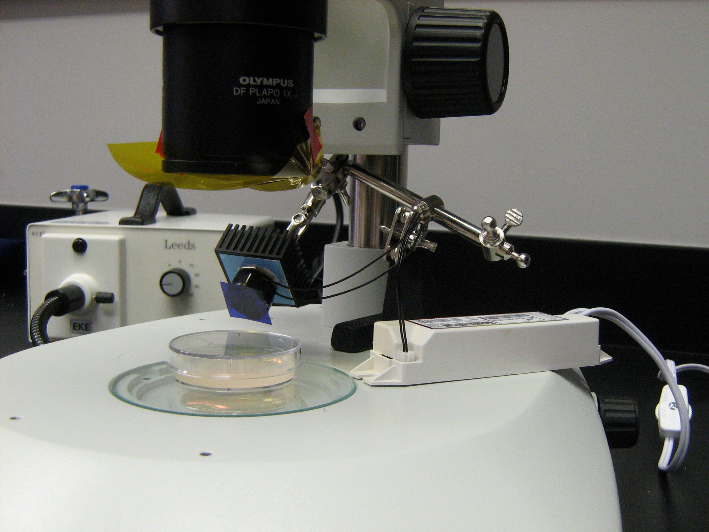
Fluorescence detection components are too costly to be installed in every stereoscope. Often, our fluorescent markers are very bright and do not require the full capacity of such equipment. Here we present an LED setup that costs only about $100 and can detect bright fluorescent markers such as myo-2::GFP. The setup (Fig. 1) consists of
- Xacto helping hands or anything that can position the LED (amazon.com)
- Lamp cord that has a switch (local hardware store)
- 17-watt Xitanium LED driver (LED Supply)
- Xitanium driver connector (LED Supply)
- Heatsink (LED Supply)
- Spot lens (LED Supply)
- Luxeon V Star optic holder (LED Supply)
- Royal-Blue Luxeon V Star LED for GFP detection (LED Supply), or Green Luxeon V Star LED for dsRED detection (LED Supply)
- Optional excitation filter: Roscolux #4290 CalColor 90 Blue for GFP, or #389 Chroma Green for dsRED (Rosco.com | Edmund Optics)
- Emission filter: Roscolux #12 Straw for GFP, or #19 Fire for dsRED (availability same as excitation filters)
When assembling the LED to the driver, make sure that the +/– ends on the LED and the neutral/line ends on the lamp cord match those on the driver. Use a non-conductive glue such as silicone adhesive (Devcon, part No.12045, local hardware store) to put the lens holder on the LED. The excitation filter can be glued to the lens by applying a small amount of glue on the edge. The emission filter can be simply taped under the microscope objective.
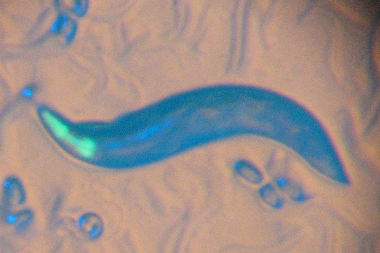
This setup has a long operating life, requires no warm-up or cool-down time, and has no radiation. However, it can only detect strong signals. We have used the setup to detect the following markers: myo-2::GFP (Fig. 2), sur-5::GFP, ajm-1::GFP, and myo-2::dsRED (Fig. 3).
More information can be found at http://130.15.90.245/gfp_stereoscope.htm and http://wormlab.rice.edu/LED.
Figures


