 Embryo series courtesy of Einhard Schierenberg
Table of Contents
DNA transformation and microinjection are essential tools for C. elegans research. Transformation is used to clone genes by mutant rescue, to over-express or ectopically express genes, to express tagged proteins, to study structure/function of protein domains, and to analyze DNA or RNA regulatory elements. Furthermore, transgenes can be powerful tools for the design of new genetic screens. Current transformation techniques generate large extrachromosomal DNA arrays, or cause "random" integration of transgenes into the genome. However, homologous recombination into endogenous loci can occur at low frequency suggesting that targeted gene replacement is possible (Broverman et al., 1993; Berezikov et al., 2004).
Microinjection is a proven and relatively simple method for introducing DNA into worms (Mello et al., 1991; Mello and Fire, 1995). Moreover, microinjection is a very effective approach to RNA interference (see Reverse genetics), and can be used to deliver synthetic mRNAs or other molecules directly to cells (Kimble et al., 1982; Bossinger and Schierenberg, 1992; Evans et al., 1994). For transformation, the relatively new technique of gene bombardment is fast becoming a popular alternative because transgenes are often integrated into the genome at low copy number, which offers a number of advantages as described below (Praitis et al., 2001; Berezikov et al., 2004).
This chapter contains protocols for microinjection of C. elegans, and for generating transgenic nematode strains by both microinjection and gene bombardment. Protocols for integration of extrachromosomal arrays into the genome are also included. This chapter focuses on the methods themselves and on some practical considerations but does not include extensive discussions of transgene dynamics, vectors, or theory. For an excellent and more thorough analysis of these issues see Mello and Fire (1995). In addition, different labs often have distinct preferences and unique modifications of these methods. The protocols below generally come from a single lab, although a few alternative modifications are included.
DNA transformation techniques typically require co-transformation with a scoreable or selectable marker gene. Transformation markers that induce a dominant phenotype allow transformation of any worm strain as long as the host's phenotype does not interfere with the marker-induced phenotype. Other selectable markers rescue lethal or non-lethal mutations and require use of specific mutant strains as transformation hosts. For some mutant rescue experiments, a co-injected marker may not be necessary but is usually advisable as a positive control for transformation. Some commonly used marker genes are listed in Table 1. For microinjection techniques, the popular choice is the pRF4 plasmid (Protocols 2 and 3). This plasmid encodes a mutant collagen (rol-6(su1006)) that induces a dominant "roller" phenotype, where animals corkscrew around in circles (Kramer et al., 1990; Mello et al., 1991). This roller phenotype is very easy to spot in a simple dissecting microscope, although there are a few potential disadvantages. The roller phenotype is suppressed in some "dumpy" (dpy) and "uncoordinated" (unc) mutant backgrounds. In addition, rollers (especially males) have reduced mating efficiency. The twisted cuticle of roller animals can also complicate live analysis of some cell types. Alternatively, one can use an unc-22 anti-sense plasmid, a mutant-rescuing plasmid, or a strongly expressed GFP fusion (Table 1; Fire et al., 1991; Granato et al., 1994; Gu et al., 1998). GFP markers require a dissecting microscope equipped with fluorescent optics. For gene bombardment, an unc-119 gene rescue system is the method of choice as described in Protocol 7.
In constructing specific transgenes, non-coding regions must be carefully considered. Obviously important domains include the 5' flanking region with its promoter and transcriptional control elements, the 3' flanking region that might contain additional elements, the 5' UTR with a functional translation start site, and the 3' UTR that provides a cleavage and polyadenylation signal and translational control elements (see Transcriptional regulation, Mechanism and regulation of translation in C. elegans). In addition, introns are important because pre-mRNA splicing promotes nuclear export, translation, and stability of mRNAs (Maniatis and Reed, 2002; Nott et al., 2004). Even purely synthetic introns substantially increase expression of reporter transgenes in C. elegans (Okkema et al., 1993). Furthermore, gene-specific regulatory elements may reside within the first few introns of some genes (see Transcriptional regulation). Proteins can be expressed from cDNAs in worms, but expression will likely be inefficient unless an intron or two is inserted into the cDNA sequence. Finally, it is important to know if the gene to be studied is trans-spliced to the SL1 or SL2 leader RNAs (see Trans-splicing and operons). For SL2-spliced genes, which are downstream in multigene operons, promoters may be several kilobases upstream and the primary transcript may encode several genes. Fortunately, most C. elegans operons have been identified and can be analyzed using Wormbase (Blumenthal et al., 2002; see Trans-splicing and operons and Web resources for C. elegans studies).
Table 1. Common markers for DNA transformation
| Marker gene | Plasmid | Marker phenotype | Advantages | Potential issues | |||||
|---|---|---|---|---|---|---|---|---|---|
| rol-6(su1006)a | pRF4 | Dominant roller | Dominant, easy to detect phenotype; known to be compatible with many co-injected transgenes | Suppressed in some mutant backgrounds (unc, dpy); reduced mating efficiency; twisted cuticle can interfere with larval lineage analysis | |||||
| unc-22 antisenseb | pPD10.46 | Dominant twitcher | Similar to rol-6 | Suppressed in some mutant backgrounds; reduced mating in males; not as easy to detect as rol-6 | |||||
| sur-5::gfpc | pTG96_2 | GFP expression in many somatic cells | Dominant visible marker; compatible with most host strains | Requires fluorescent dissecting scope; interferes with expression study of other GFP fusions | |||||
| pha-1(wt)d | pC1,pBX | pha-1(e2123ts) rescue | Allows selection of transformed worms; likely to work in most mutant backgrounds | Requires pha-1(ts) as host strain, which is maintained at 15°C; selection requires growth at 25°C | |||||
| unc-119(wt)e | Variouse | unc-119(ed3) rescue | Allows selection of transformed worms; useful for enrichment of integrants after bombardment | Requires unc-119(lf) as host strain; selection process takes longer | |||||
References:
|
|||||||||
Introduction and considerations. Microinjection is an effective method for creating transgenic animals, for RNAi of selected genes, and for introducing various types of molecules directly to cells. For DNA transformation, the easiest approach is to inject DNAs into the distal arm of the gonad (Figure 1; Mello et al., 1991; Mello and Fire, 1995). The distal germ line of C. elegans contains a central core of cytoplasm that is shared by many germ cell nuclei (see Introduction to the germ line). Therefore, DNAs injected here can be delivered to many progeny. This approach usually leads to the formation of large extrachromosomal DNA arrays (Mello et al., 1991). Microinjection directly into oocyte nuclei can induce chromosomal integration of transgenes, but this technique is relatively difficult to do (Fire, 1986). For RNAi experiments, most progeny of injected animals can be affected by simply injecting dsRNA into a single gonad or intestinal cell because of a very efficient RNA transport system (see Reverse genetics). While RNAi by feeding is best for high throughput experiments, RNAi by microinjection is more effective for at least some genes (see Reverse genetics). Contrary to common perceptions, nematode microinjection is not hard to learn and does not require the most expensive equipment. The microinjection method described below is geared towards generating transgenic worms, but it can be readily adapted for injecting a variety of molecules into various locations.
Modified from Mello et al. (1991); Mello and Fire (1995).
Injection table. A heavy table segregated from strong vibrations and air currents is usually sufficient. If vibration is a problem, a heavy metal slab placed on a set of small, partly inflated, tire inner tubes can help.
Inverted DIC microscope. A Zeiss Axiovert, or equivalent Nikon or Olympus instrument, equipped with standard 5X and 40X Nomarski objectives (non-oil immersion) is sufficient. Top of the line optics are not necessary. The microscope should have a flat, free-sliding glide stage with centered rotation.
Micromanipulator. Narashige, Leitz, and Zeiss make sufficient manipulators that can hold and position the needle holder. The ideal manipulator will have fine mobility in the X (forward and back), Y (side to side), and Z (vertical) axes, and allow easy alteration of needle angle and position.
Pressurized injection system with needle holder. The injection needle is placed in a holder with a tight-seal collar, which is then attached by plastic tubing to a regulated pressure source. The pressure regulator is attached to a nitrogen gas tank. A Narishige or Eppendorf microinjection controller equipped with a foot pedal switch is a good but somewhat expensive choice. Tritech (Los Angeles, CA) makes a less expensive system. Mello et al. (1991) describe a homemade system.
Needle puller. Sutter instruments P-87 and P-97 microelectrode pullers are excellent for making very consistent needles of specific shapes and sizes, although a variety of other microelectrode pullers can be used. Several labs can easily share a single puller.
A standard dissecting microscope.
Microinjection needles. Pull needles using borosilicate glass capillaries (1.0mm OD, 0.75 mm ID) with a fine internal glass filament, which allows backfilling by capillary action (e.g., FLG10 from Dagan Corp., Minneapolis MN; or equivalent from World Precision Inst., Sarasota FL or Clark Inst., Reading, England). Good needles taper quickly (~5-7 mm) to a sharp but open point (≥1 um), although each user may develop unique preferences. For needle pullers that produce a closed tip, break open the tip by gently tapping the needle across a glass slide, or by moving the needle against debris on the agarose pad under the microscope (see below).
Injection pads. Bring 2% agarose in water to a boil, mix well, and place in a heat block. Using a broken Pasteur pipette or a cut-off P200 tip, place a drop (~100ul) of hot agarose onto a #1, 50X22-mm glass coverslip. Quickly place a second coverslip on the drop and lightly tap it. Alternatively, place several drops on the first coverslip, which should merge and mostly cover the surface after adding the second coverslip; such pads can be used for several rounds of injection (Mello and Fire, 1995). After the agarose is solidified, peel or slide coverslips apart, and bake the coverslip-pad in a vacuum oven at 80°C for 1h to overnight. Alternatively, injection pads can be air dried overnight, but worms may not stick well in humid climates. Bake or even re-bake the pads before use if worm adherence is chronically poor. Higher agarose concentrations (2.5-3%) can increase worm adhesion but will also increase their rate of drying out (see below).
Injection oil. Series 700 Halocarbon oil (Halocarbon Products, River Edge, NJ). Alternatively, Heavy Paraffin Oil can be used (BDH Chemicals, Poole, England; Gallard-Schlesinger, Carle Place, NY).
Worm pick. A worm pick with a very flat, narrow, arrow-shaped head works best.
Recovery buffer and M9 buffer. Recovery buffer: 5mm HEPES pH 7.2, 3 mM CaCl2, 3 mM MgCl2, 66 mM NaCl, 2.4 mM KCl, 4% Glucose (w/v). Standard M9 Buffer.
Worms. Well-fed, young to middle-aged (≥1day old) gravid hermaphrodites with a full but single row of eggs are best.
Needle-loading pipettes. Place a 10ul standard glass capillary pipette over a flame until it softens, then remove from flame and quickly pull out and break to generate two drawn out pipettes. Use mouthpiece and tubing for ejecting solution. Alternatively, a p2 pipettor can be used to load needles.
Fill a needle-loading pipette by capillary action with ≥ 1 ul of DNA injection mix.
Insert the pipette tip in through the back of the injection needle, and expel injection mix onto the needle's internal filament. Watch to see that the injection solution is drawn into the needle tip. Several injection needles can be prepared and stored by resting them across raised clay or wax ridges in a humid box with lid.
Place a loaded needle into the needle holder and mount on the manipulator.
Position the needle so that the tip is in the center of the microscope's field of view using the 5X objective. Once positioned, move the needle up (using the Z-axis control) so that it is slightly out of focus.
Place a drop of oil on an injection pad and place under a dissecting microscope on top of a small Petri plate cover.
Scoop one to several worms from a bacteria-free region of an NGM plate with a naked pick and transfer to the oil drop. Avoid contact with the worm's head. Alternatively, first touch the worm pick to the oil, and use the oil droplet to pick up the animals from a bacteria-free region. The idea is to minimize transfer of bacteria to the pad.
Flame then cool the worm pick and use it to position the worms in the oil drop, and to gently push them down onto the pad. Orient the worms in rows with their ventral sides facing the same direction (opposite the needle direction). If the worms fail to adhere to the pad, move to a new location or rub the bodies with the pick to remove water or bacteria droplets. If adherence is still a problem re-bake the pads or use thicker or higher concentration agarose pads (see above).
Transfer the slide face-up onto the microscope stage. Center the first worm to be injected and focus using the 5X objective. Move the needle down and in close proximity to the dorsal surface of the first animal. Switch to the 40X objective and focus on the worm.
First make sure the needle is flowing: Move the needle down into focus. Then move the stage a little to move the worm away from the needle. Apply pressure to test if there is significant flow. If not, the needle is probably clogged. In this case, try a pulse of high pressure (but don't exceed the pressure tolerance of the system, which will cause needle ejection and possibly gasket damage). If this fails to work, focus down onto a piece of debris on the pad and move the needle tip gently down onto the pad surface. With the pressure applied, drag the stage away from the needle; often this will remove junk on the tip and induce flow without breaking the tip. Stop flow and move the needle up off the pad if flow resumes. If this doesn't work, break the tip by gently contacting a particle embedded within the pad while under pressure. Rub the particle across the needle tip by moving the stage. If this doesn't work, or if too much of the needle tip breaks off, mount a new needle. Worms can often tolerate broken needles with fairly large openings, but there is a limit that requires experience to determine.
Insert the needle into the worm: Move the first worm back to the center of the field ("moving the worm" always means moving the stage). Position the worm so that its dorsal surface lies at a sharp angle to the needle (~15°-45°; Figure 1). Focus the objective on birefringent particles in the distal core cytoplasm of one gonad arm, at its widest point if possible (Figure 1). Using the manipulator, move the needle tip into the same focal plane directly adjacent to the targeted location. Push the worm up against the needle tip until the cuticle distends inward (i.e. is depressed), and then push the worm slightly back against the needle, into the tip, until the needle inserts into the core. The idea is to "pinch" a bit of cuticle and then push against the pinch, like a hypodermic needle into skin, except the stage is used to move the worm into a stationary needle. Alternatively, one can push the worm into the needle at a right angle, and then gently tap on the manipulator to induce insertion (Mello and Fire, 1995). Note: Usually one gonad is easier to see than the other, but with practice both gonads can usually be injected.
|
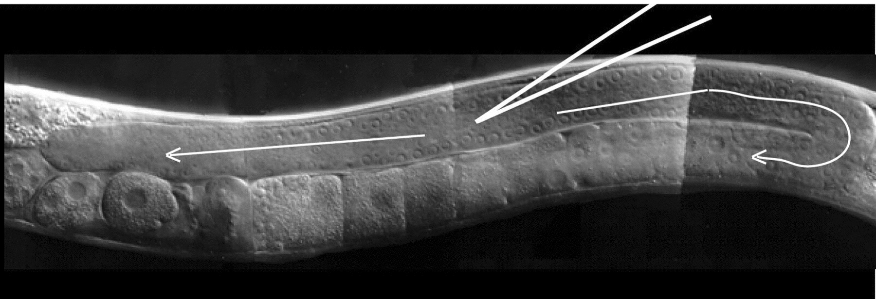
Figure 1. Microinjection of the C. elegans gonad. The optimal position of the injection needle in the cytoplasmic core of the distal germ line is depicted. For DNA transformation, injection solution should flow in both directions through both the distal and proximal germ line (arrows). Note: The optimal hermaphrodite would be several hours older than the one shown here, with a larger gonad syncytium that has a larger, more obvious cytoplasmic core.
Inject the DNA solution. Using the fine X-axis control, position the tip into center of the cytoplasmic core. Apply pressure so that solution flows freely and smoothly in both directions throughout the gonad until the gonad noticeably swells up (Figure 1; see also Figure 1 of Mello and Fire, 1995). If solution does not flow into the core, a gentle tap on the table can often help. For DNA transformation, the best results seem to occur when the gonad is filled seemingly to the point of damage. Stop the flow at this point and pull the worm off the needle. Test the needle for flow again and then move to the next worm and repeat steps 10 and 11. Unclog or break the needle tip if necessary (step 9).
Recover the worms: Return the coverslip to the dissecting scope, and add a drop (~20 ul) of recovery buffer on the worms. Make sure buffer surrounds the worms so that they release off of the pad. Transfer coverslip to a large empty Petri dish, cover, and incubate for 10-60 min. Once the worms begin swimming briskly, M9 can be added; add an approximately equal volume of M9 and wait until worms swim briskly again, then repeat several times until the solution is mostly M9. The idea is to gradually change the osmotic strength over several minutes. Note: Worms that have not dried too much can often be recovered quickly by directly adding M9 (Mello and Fire, 1995), although in our experience survival is highest using recovery buffer. Transfer the worms to seeded plates.
Troubleshooting. An excellent troubleshooting guide is presented in Mello and Fire (1995). A few highlights are: (a) If the worm ruptures or dies after injection, the needle may be too big, there was too much tearing, or the worm became too dried out; try injecting only one gonad per animal with a fresh needle. Another less likely cause is a contaminated DNA mix (e.g., phenol). (b) If the animals fail to stick, the pads may be too thin or need to be baked (see above). Also, try drying the worm plates by placing coverless in a hood for a few hours. (c) If the worms dry out too fast, use thinner pads and/or transfer worms to moist fresh plates before injection. (d) If the injections look good but no transformants arise, the DNA prep may be dirty (a common problem) or the transgene may induce lethality (see below).
The easiest approach to make transgenic strains is to co-inject two or more DNAs into the distal gonad syncytium; one or more DNAs carrying the intended transgenes and a plasmid carrying a transformation marker. Transgene DNAs can be plasmids, cosmids, phage, YACs, or PCR products. Injected DNAs undergo homologous recombination with each other quite efficiently, so it is not necessary to physically link them before injection (Mello et al., 1991). For this reason, it works best if the injected DNAs share sequence homology in their backbones, although non-homologous recombination also occurs (Mello and Fire, 1995). It is feasible to inject several DNAs and recover animals carrying all injected molecules. Whether the injected DNA is circular or linear does not seem to influence results.
Transgenic animals produced by injection typically carry large extrachromosomal arrays that contain many copies of the co-injected DNAs. These repetitive arrays are usually unstable to cell division but can become inheritable; a fraction of first generation progeny (F1) that contain the transgenes will transmit the array through many subsequent generations often without changes in heritability or expression (for somatic promoters). These heritable arrays still have varying degrees of mitotic instability and incomplete inheritance, although it is possible to integrate transgenic arrays into chromosomes (see Protocols 4-6).
Advantages. This technique is relatively fast and efficient for genes expressed in somatic tissues; an experienced person injecting simple plasmids can generate 3-6 independent transgenic lines in 7-10 days from as few as 15-40 injected gonads. (If the transgene causes a deleterious phenotype or if large genomic fragments are used, the success rate can be lower). All that is needed is a plate of well-fed hermaphrodites and a few microliters of purified plasmids, and multiple constructs can be analyzed in a reasonable time frame. In addition, the mitotic instability of these arrays can actually be used to create genetic mosaics, which can then be analyzed to determine the lineages in which a gene functions (Herman, 1995), see Genetic mosaics.
Disadvantages. (1) The transgene expression pattern may not mimic the endogenous gene, especially for germline-expressed genes. Transgenes in repetitive arrays are strongly silenced in germ cell nuclei (Kelly et al., 1997). In addition, suppressed or ectopic transgene expression is sometimes observed in somatic tissues (Mello and Fire, 1995). Rescue of a null mutant does not assure proper expression since even suppressed or ectopically expressed genes can give rescue. (2) It is difficult to predict and control the level of expression among different arrays. (3) Transgene expression can be variable among siblings of a single strain. Some variability probably relates to mitotic instability of arrays, but even integrated arrays can show expression variability for unknown reasons (Mello and Fire, 1995). (4) Arrays sometimes induce RNAi-like effects that suppress endogenous gene function (Dernburg et al., 2000). This could be due to DNA rearrangements during array formation that cause production of gene product fragments or antisense RNA (T. Evans and J. Kimble, unpublished). DNA rearrangements can also reposition gene regulatory elements leading to mis-regulated transgenes. Rearrangements may also occur during long term passage of some transgenic strains, since sometimes the properties of transgenic animals changes over time (T. Evans, unpublished). In spite of these pitfalls, many well-behaved transgenic strains have been created by this technique. Integration of arrays can minimize problems associated with transmission instability (Protocols 4-6). Therefore, as long as caution is exercised this remains a very important approach to nematode transformation.
Modified from Mello and Fire (1995).
Purify DNAs for injection: Standard alkaline lysis protocols, including commercial kits, are sufficient for plasmids and cosmids although residual contaminants can prevent transformation. To generate clean DNA preps, do extra washes in the commercial column-based procedures and/or further purify DNA by phenol choloroform extraction, G-50 spin column, chloroform extraction, and ethanol precipitation. Miniprep procedures that use LiCl or CTAB precipitation steps are also effective for transgene DNAs (Fire et al., 1990; Mello and Fire, 1995). Protocols for preparing YACs and phage for injection can be found in Mello and Fire (1995). DNAs can be stored in standard Tris/EDTA (TE) buffer.
Mix transgene DNA (to 1-100 ug/ml final concentration) with pRF4 (or other marker; to 100 ug/ml). Dilute DNAs with sterile water or TE. Use lower transgene concentrations if the gene is toxic or if multiple plasmids/cosmids are used. Strive for a total DNA concentration of 100-200 ug/ml. An empty vector (e.g., Bluescript) can be used to reach this goal if desired.
Inject 15-50 gonads for each DNA mix as described in Protocol 1.
Transfer each injected worm to a separate, seeded NGM plate. Grow at 20-25°C.
When F1 progeny reach L3 to L4 stages, pick rollers to new plates, 2-3 rollers per plate. Continue to pick more rollers over the next day or two if necessary. Make sure to label plates to identify the parent for each plate.
Look for plates that produce F2 rollers and clone several F2 rollers from those plates. Typically, ~2-15% of F1 rollers will transmit the array to the F2 generation. Most F2 rollers will generate lines that continue to transmit their array at a consistent frequency, which can be 5-95% (30-60% is common). Keep only one strain from each injected parent, since lines from the same parent may not be independent transformants.
Germline silencing of repetitive transgene arrays depends at least partly on their repetitive sequences (Kelly et al., 1997). To circumvent this problem, fragmented genomic DNA can be added to injection mixes, which presumably limits formation of tandem repeats that silence chromatin in the germ line (Kelly et al., 1997). Such "complex" arrays incorporate transgene DNA, marker DNA, and genomic fragments without prior ligation, presumably due to non-homologous recombination. For this technique, DNA linearization seems to be important. These complex arrays, like repetitive arrays, are carried as heritable extrachromosomal fragments with varying degrees of germline transmission. For unknown reasons, germline expression from complex arrays can disappear after the first few generations even in strains that retain the array. Maintaining animals at 25°C suppresses transgene inactivation (Reese et al., 2000; Strome et al., 2001). A fraction of transgenic strains can maintain strong germline expression for many generations.
Advantages. The primary advantage of this technique is that it allows analysis of germline-expressed transgenes that do not work in repetitive arrays. It is relatively quick, inexpensive, and simple compared to gene bombardment protocols described below.
Disadvantages. Germline expression can become silenced after a few generations. In addition, because the number of transgenic animals recovered is low and only a small percentage of these will continue express the transgene, many animals must be injected. Complex arrays can also induce phenotypes in some transgenic strains, which probably depends on the combination of genomic fragments in the array. For similar reasons, various ectopic expression patterns are often detected in these transgenic strains.
(From Geraldine Seydoux and Kelly et al., 1997)
Make a DNA injection mix:
| Transgene plasmid, linearized | 1ug/ml |
| pRF4, cut with EcoRI | 1ug/ml |
| N2 genomic DNA, cut with ScaI | 60ug/ml |
Inject 30–60 hermaphrodites (50–100 gonads).
Transfer 1-3 injected animals per plate, and grow them at 25°C.
Clone F1 rollers to individual plates and grow at 25°C. Typically, 15–50 F1 rollers will be obtained, and 10–30% of these will give F2 rollers. Examine these F2 rollers as germline expression often diminishes in subsequent generations. Keep animals at 25°C to minimize this effect.
Extrachromosomal arrays can be integrated into a chromosome to help mitigate their genetic instability and variability. Three protocols for integrating arrays are described below. Two methods use irradiation of existing transgenic strains, which presumably induces chromosomal breaks and ligation of arrays to chromosomes during DNA repair. Because of this, mutations can arise in treated animals, so it is wise to outcross the recovered integrated strains by mating with wild type males (see Genetic mapping and manipulation). In most cases, integrated arrays retain their multicopy character, thus problems associated with repetitive sequences will remain (see Protocol 2). A third method involves co-injecting transgene DNAs with a single stranded DNA oligonucleotide (Mello et al., 1991). The oligo apparently stimulates random integration and/or suppresses array formation. The primary advantage of this approach is that an integrated line can be directly derived from injected animals, but transformation efficiency is reduced about 10-fold.
(From Peg MacMorris)
Choose a transgenic roller line with ≤50% transmission frequency (if possible). Note: Some people irradiate 2-3 lines to increase the probability of isolating a well-behaved integrant (Mello and Fire, 1995).
For each strain, take 200-300 L4 rollers, or a mixed population with several hundred L4 rollers washed into M9 buffer, and irradiate with 3800 Rad from a 137Cesium source. (Each 137Cs source will have it's own instructions).
Transfer worms to seeded plates for several hours of recovery. Plate pools of about 20 irradiated young roller adults on 10 large (10cm) seeded plates. Grow at 20-25°C.
After the food is exhausted, transfer worms by washing each plate with 5ml M9, and drop ~0.1-0.5ml to each of another set of 10 seeded plates. Grow at 20-25°C. Repeat this step at least one time.
Clone 10 rollers from each plate and screen the progeny of these animals for clones with 100% roller progeny. (Note: It is important to screen the plates before the worms have starved).
Outcross the suspected integrated lines by mating to N2 males. The integrated array should segregate like a dominant chromosomal mutation.
(From Ji Ying Sze)
Pick 30 L4 rollers to each of two plates.
Place the plates in a Stratagene UV crosslinker (Stratalinker), with the lids removed. Set the power to 300 and push start. (Note: UV bulb energy can decrease with time according to Stratagene).
Transfer worms to seeded plates.
Clone 200-300 F1 rollers. Then, screen these plates for those that have high transmission to the F2 progeny. Clone 7-8 F2 animals from "high transmitting" F1's, clone a few from "intermediate transmitters", and discard the rest. Keep plates producing 100% inheritance, which are likely to contain homozygous integrants.
Outcross the suspected integrants.
(From Mello et al., 1991)
Injection mix: transgene plasmid + co-transformation marker (50-100 ug/ml total) + 1 mg/ml single stranded DNA oligo. The oligo sequence may not be important, but a 50mer that is known to work has been described (Mello et al., 1991). Inject 100-200 gonads as in Protocol 1. Recover worms and place 2-3 worms on seeded plates. This procedure typically yields 5-10 heritable lines, one or two of which are integrants with 1-10 transgene copies.
A significant advance in nematode transgenics was the discovery that microparticle bombardment can induce integrative transformation in C. elegans (Praitis et al., 2001). With this technique, DNA is bound onto gold particles which are then "shot" into worms using a biolistic bombardment instrument or "gene gun". A significant number of transformants generated this way are integrants, and many of these contain only a few copies of the transgene. Perhaps these low copy integrants arise because some DNA-coated particles enter nuclei, since similar integration events are seen following direct injection of DNA into oocyte nuclei (Fire, 1986; Praitis et al., 2001). Particle bombardment will also generate extrachromosomal arrays, but using the unc-119 gene as a selectable marker helps to enrich for integrants (Praitis et al., 2001). The unc-119 (ed3) mutant is viable and uncoordinated, but cannot survive dauer formation (Maduro and Pilgrim, 1995). Therefore, unc-119 (ed3) animals transformed with a wild type unc-119 gene will survive starvation while non-transformed animals and those that have lost unstable arrays will not survive. Many rescued unc-119 animals grown this way carry transgenes integrated at various non-homologous sites in the genome. It is not known if there are integration hot spots. For this technique, the transgene must be subcloned into the same plasmid with the unc-119 selectable marker.
Advantages. Stable integrated transgenic strains can be isolated directly. Moreover, many integrated transgenes do not undergo germline silencing and germline expression can remain stable (Praitis et al., 2001). In addition, low copy integrants are likely to avoid some of the other pitfalls of the repetitive and sometimes jumbled sequences in arrays (see Protocol 2 above). Transgenes integrated at low copy give the researcher more control over gene dosage and strain construction in various genetic backgrounds. Expression variability is also less of a problem with these low copy integrants (Praitis et al., 2001). Finally, scaled-up bombardment allows isolation of strains with homologous gene replacements (Berezikov et al., 2004).
Disadvantages. The preparation of nematodes and materials for gene bombardment is significantly more labor and material intensive than for microinjection, and it takes longer to generate transgenic strains. Gene bombardment is relatively expensive, as it requires access to a gene gun (~$17,000) and a steady supply of pricey materials. Nonetheless, the potential payoffs will make these investments worthwhile for some researchers.
(From C. DeRenzo, D. Ghosh, A. Cuenca, M. Stitzel, and G. Seydoux; adapted from Shai Shaham, personal comm., and Praitis et al., 2001)
| Equipment/material | Company | Cat. # |
| Biolistic PDS-1000/He particle delivery system | Bio-rad | 1652257 |
| Hepta Adapter, biolistic | Bio-rad | 1652225 |
| Biolistic Macrocarriers | Bio-rad | 1652335 (500 ct) |
| 1μM gold beads | Bio-rad | 1652263(0.25gm) |
| Rupture Discs | Bio-rad | 1652333 (2000psi) |
| Hepta Stop Screen | Bio-rad | 1652226 (50ct) |
| Spermidine(tissue culture grade) | Sigma | S-4139 (5.0 gm) |
| Nystatin | Sigma | N1638 (100mls) |
Enriched Peptone Plates (1 Liter)
| 1.2g sodium chloride |
| 20g peptone |
| 25g agar |
| water to 1 liter |
Autoclave, then cool to 55°C and add sterile:
| 1ml cholesterol (5mg/ml in EtOH) |
| 1 ml 1M MgSO4 |
| 25 ml 1M potassium phosphate (pH 6.0) |
| water to 1 liter |
Enriched Peptone Plates with nystatin (1 Liter)
Use the same recipe as above and add 10mls Nystatin suspension (10,000 units/ml).
Day 1: Master plate
Seed 50–100 unc-119 (ed3 or ed4) worms on an enriched peptone plate with NA22 bacteria spread evenly over the entire plate (use enriched peptone plates with NA22 bacteria throughout this protocol). Either pick worms on several different spots or evenly spread out worms, suspended in M9 buffer. Let the worms grow until they have starved for 2-3 days (~7 days total). The plate now contains numerous worm colonies, which consist mainly of L1s. Always have master plates ready when planning bombardments since unc-119 worms are slow growing.
Day 7: Amplify worms to 6–7 plates
Wash worms off the master plate with M9 buffer. Repeat the wash step until most of the bacteria is gone. Resuspend worms in 6-7 ml M9 buffer and spread 1.0 ml onto each of 6-7 plates. Allow worms to grow and starve to L1s (2 days). These plates now contain ~ 2-4 x 10⁶ L1s.
Day 9: Amplify worms to 60 plates
Wash off worms from 6-7 plates with M9 buffer until most of the bacteria is gone. Resuspend worms in 60 ml buffer. Add 1ml worms to each plate; spread worms evenly by holding 5 plates a time and gently rotating the stack. Let the worms grow for 2.5-3 days at 20°C or 2 days at 25°C (until they become young adults).
Day 12: DNA preparation
Weigh 35-50 mg of 1 μm gold beads (Biorad) into a siliconized 1.5 ml eppendorf tube.
Add 1ml 70%EtOH. Vortex 5 minutes. Soak for 15 minutes. Pellet and remove sup.
Add 1ml sterile water. Vortex 1 minute. Soak for 1 minute. Pellet and remove sup.
Add 1ml sterile water. Vortex 1 minute. Soak for 1 minute. Pellet and remove sup.
Add 1ml sterile water. Vortex 1 minute. Soak for 1 minute. Pellet and remove sup.
Resuspend in 500 μl sterile 50% glycerol. This bead stock can be used for 2 weeks (or more) and should be stored at 4 °C.
Vortex mix for 5 minutes. Transfer 100 μl of bead suspension into 3 eppendorf tubes. Make sure to keep the gold beads in suspension while transferring; vortex the stock suspension at medium speed, stop, and then immediately transfer 100 μl to each tube.
For each of the three tubes, add in order while vortexing on medium speed:
| 10 μl DNA (1 mg/ml) |
| 100 μl 2.5 M CaCl2 |
| 40μl 0.1 M spermidine (free base, tissue culture grade) |
Vortex 2 minutes. Soak for 1 minute. Pellet and remove sup.
Add 280 μl 70% EtOH. Flick tube to mix. Pellet and remove sup.
Add 280 μl 100% EtOH. Flick tube to mix. Pellet and remove sup.
Add 96 μl 100% EtOH and resuspend by gently flicking tube. This is your prepped DNA. Do this before preparing worms (below).
Day 12: Worm preparation
Wash the 60 plates with M9 buffer into 50ml tubes (~400mls/60plates). Spin at low speed for 1 minute; wash worms until the M9 solution becomes clear and finally transfer worms to a 15ml tube. Spin again at low speed for 1 minute. This should give you a pellet of 2-4 ml packed worms. Remove liquid and resuspend worms to 10ml with M9.
Day 12: Bombardment
Using a short pasteur pipette, transfer ~ 1.5 ml of worms to the surface of a dry (1 week post bacterial spreading) enriched peptone plate. Add them drop wise starting at the center and then spiraling around until you reach the edge of the plate. Repeat until all worms are plated (6 plates).
Leave the covers off the plates to evaporate the liquid. This should take no more than 15 minutes. If it takes more, the enriched peptone plates are too wet.
While the plates dry prepare the gene gun. We use the BioRad Biolistic PDS-1000/He particle delivery system with the Hepta adaptor. This adaptor saves an enormous amount of time and effort. Illustrations and jargon definitions are found in the BioRad manual. Read this manual to be familiar with the procedures described below.
Hook the vacuum tubing to a vacuum source port (with plastic adaptor). Open vacuum port. Turn on gene gun. Open helium tank valve (check to make sure that He tank pressure is ≥ 2200psi). Perform a test bombardment by wetting a rupture disk (1500-2000 psi) in isopropanol, placing in retaining cap for hepta adaptor, and tightening onto bombardment chamber.
Close door. Pull vacuum to 27 in of Hg. Once it reaches 27 in of Hg press hold. Press Fire button and hold until disk ruptures. Release vacuum (Vent position), open door, unscrew retaining cap and discard the ruptured disk.
Place 7 macrocarriers onto the hepta adaptor macrocarrier holder using the special tool. Vortex your DNA preparation at medium speed with cap open. Stop and immediately (quickly) transfer 6 μl of beads onto a macrocarrier and spread it around with your pipette tip. Only spread on area around the hole in the holder. Repeat for all macrocarriers. Let EtOH evaporate (this only takes a few minutes).
Place a rupture disk soaked in isopropanol in the retaining cap and tighten. Place hepta stopping screen and macrocarrier holder in chamber as described in manual. Place uncovered worm plate (taped to the sample holder using a rolled piece of adhesive tape to create double sided tape) into lowest rung in bombardment chamber.
Evacuate chamber to 26 in Hg. Press Fire button until disk ruptures. Release vacuum (Vent position), and remove plate.
Repeat above for all 6 plates.
Turn off the vacuum. Close the helium tank valve - make sure no pressure is left in the line. Turn the gene gun power OFF.
**Wipe down all of the gene gun components with 70% ethanol, then autoclave the hepta adaptor and the macro carrier holder components. Wipe down the bombardment chamber with 70% ethanol.
Day 12: Plating worms
Wash bombarded worms off plates with M9. Place worms in 50ml tubes. Spin 1 minute at low speed. Resuspend worms evenly in 2 tubes with 80 ml of M9 media.
Plate worms, 1ml per plate, enriched peptone plates with nystatin and seeded with NA22 bacteria. Should end up with ~80 plates.
Once plates have dried, place them in a 25° C incubator (we found this to be important for GFP expression of several germline genes, you can grow worms at 20°C for non-GFP transgenes) and let sit for 10-14 days (preferably in a plastic containers to avoid plates drying out).
Day 22–26: Screening
Scan plates for WT animals. Typically, 10-20 plates contain WT animals with anywhere from 1 to many WT animals per plate.
From each big plate, clone 3-5 WT worms to individual plates (regular NGM plates with OP50). Place the plates a 25° C for 4 days, and then examine the progeny for GFP expression.
Current transformation technology is powerful for the analysis of gene function and regulation in C. elegans. However, the holy grail of DNA transformation is targeted gene replacement by homologous recombination. As shown in yeast and mice, gene targeting can create null mutations in virtually any selected gene (gene knock-out), and can replace genes with designed derivatives (gene knock-in). Homologous recombination of transgenes into endogenous loci was observed in some C. elegans strains when DNA was injected into oocyte nuclei (Broverman et al., 1993). By scaling up gene bombardment procedures, Berezikov et al. recently isolated a few knock-out homologous integrants, and one knock-in replacement (Berezikov et al., 2004). These exciting results suggest that gene targeting may be feasible by microparticle bombardment. A limitation is that only ~0.5%-7% of integration events arise from homologous recombination, and it is not clear what parameters might affect these rates. Perhaps new transgene designs or isolation of mutants with increased recombination rates will soon lead to routine procedures for this powerful technology.
This chapter would not be possible without the generous contributions of the experts in these methods. Many thanks are due to Cyndy DeRenzo, Peg MacMorris, Eric Moss, Geraldine Seydoux, and Ji Ying Sze, for contributing protocols and unpublished information, and to David Fay, Andy Fire, Barth Grant, Wade Johnson, Chris Link, Morris Maduro, Craig Mello, and Ding Xue for valuable information and advice. Thanks are also due to the entire C. elegans community for their collective efforts that make these techniques work. Work in T.C.E's laboratory was supported by grants from NSF (9982944, 0345386), U. Colo. Cancer Center and ACS, and NIH (GM20599-03).
Berezikov, E., Bargmann, C.I., and Plasterk, R.H. (2004). Homologous gene targeting in Caenorhabditis elegans by biolistic transformation. Nucleic Acids Res. 32, e40. Abstract Article
Blumenthal, T., Evans, D., Link, C.D., Guffanti, A., Lawson, D., Thierry-Mieg, J., Thierry-Mieg, D., Chiu, W.L., Duke, K., Kiraly, M., and Kim, S.K. (2002). A global analysis of Caenorhabditis elegans operons. Nature 417, 851–854. Abstract Article
Bossinger, O., and Schierenberg, E. (1992). Cell-cell communication in the embryo of Caenorhabditis elegans. Dev. Biol. 151, 401–409. Abstract Article
Broverman, S., MacMorris, M., and Blumenthal, T. (1993). Alteration of Caenorhabditis elegans gene expression by targeted transformation. Proc. Natl. Acad. Sci. USA 90, 4359–4363. Abstract
Dernburg, A.F., Zalevsky, J., Colaiacovo, M.P., and Villeneuve, A.M. (2000). Transgene-mediated cosuppression in the C. elegans germ line. Genes Dev. 14, 1578–1583. Abstract
Evans, T.C., Crittenden, S.L., Kodoyianni, V., and Kimble, J. (1994). Translational control of maternal glp-1 mRNA establishes an asymmetry in the C. elegans embryo. Cell 77, 83–194. Abstract Article
Fire, A., Albertson, D., Harrison, S.W., and Moerman, D.G. (1991). Production of antisense RNA leads to effective and specific inhibition of gene expression in C. elegans muscle. Development 113, 503–514. Abstract
Fire, A., Harrison, S.W., and Dixon, D. (1990). A modular set of lacZ fusion vectors for studying gene expression in Caenorhabditis elegans. Gene 93, 189–198. Abstract Article
Granato, M., Schnabel, H., and Schnabel, R. (1994). pha-1, A selectable marker for gene transfer in C. elegans. Nucleic Acids Res. 22, 1762–1763. Abstract
Gu, T., Orita, S., and Han, M. (1998). Caenorhabditis elegans SUR-5, a novel but conserved protein, negatively regulates LET-60 Ras activity during vulval induction. Mol. Cell Biol. 18, 4556–4564. Abstract
Herman, R.K. (1995). Mosaic analysis. Methods Cell Biol. 48, 123–146. Abstract
Kelly, W.G., Xu, S., Montgomery, M.K., and Fire, A. (1997). Distinct requirements for somatic and germline expression of a generally expressed Caernorhabditis elegans gene. Genetics 146, 227–238. Abstract
Kimble, J., Hodgkin, J., Smith, T., and Smith, J. (1982). Suppression of an amber mutation by microinjection of suppressor tRNA in C. elegans. Nature 299, 456–458. Abstract Article
Kramer, A. (1996). The structure and function of proteins involved in mammalian pre-mRNA splicing. Annu. Rev. Biochem. 65, 367–409. Abstract Article
Kramer, J.M., French, R.P., Park, E.C., and Johnson, J.J. (1990). The Caenorhabditis elegans rol-6 gene, which interacts with the sqt-1 collagen gene to determine organismal morphology, encodes a collagen. Mol. Cell Biol. 10, 2081–2089. Abstract
Lewis, J.A., and Fleming, J.T. (1995). Basic culture methods. Methods Cell Biol. 48, 3–29. Abstract
Maduro, M., and Pilgrim, D. (1995). Identification and cloning of unc-119, a gene expressed in the Caenorhabditis elegans nervous system. Genetics 141, 977–988. Abstract
Maniatis, T., and Reed, R. (2002). An extensive network of coupling among gene expression machines. Nature 416, 499–506. Abstract Article
Mello, C., and Fire, A. (1995). DNA transformation. Methods Cell Biol. 48, 451–482. Abstract
Mello, C.C., Kramer, J.M., Stinchcomb, D., and Ambros, V. (1991). Efficient gene transfer in C.elegans: extrachromosomal maintenance and integration of transforming sequences. EMBO J. 10, 3959–3970. Abstract
Nott, A., Le Hir, H., and Moore, M.J. (2004). Splicing enhances translation in mammalian cells: an additional function of the exon junction complex. Genes Dev. 18, 210–222. Abstract Article
Okkema, P.G., Harrison, S.W., Plunger, V., Aryana, A., and Fire, A. (1993). Sequence requirements for myosin gene expression and regulation in Caenorhabditis elegans. Genetics 135, 385–404. Abstract
Praitis, V., Casey, E., Collar, D., and Austin, J. (2001). Creation of low-copy integrated transgenic lines in Caenorhabditis elegans. Genetics 157, 1217–1226. Abstract
Reese, K.J., Dunn, M.A., Waddle, J.A., and Seydoux, G. (2000). Asymmetric segregation of PIE-1 in C. elegans is mediated by two complementary mechanisms that act through separate PIE-1 protein domains. Mol. Cell 6, 445–455. Abstract Article
Strome, S., Powers, J., Dunn, M., Reese, K., Malone, C.J., White, J., Seydoux, G., and Saxton, W. (2001). Spindle dynamics and the role of γ-tubulin in early Caenorhabditis elegans embryos. Mol. Biol. Cell 12, 1751–1764. Abstract
*Edited by Victor Ambros. Last revised March 04, 2005. Published April 6, 2006. This chapter should be cited as: Evans, T. C., ed. Transformation and microinjection (April 6, 2006), WormBook, ed. The C. elegans Research Community, WormBook, doi/10.1895/wormbook.1.108.1, http://www.wormbook.org.
Copyright: © 2006 Thomas C. Evans and contributors. This is an open-access article distributed under the terms of the Creative Commons Attribution License, which permits unrestricted use, distribution, and contributors reproduction in any medium, provided the original author and source are credited.
§To whom correspondence should be addressed. E-mail: tom.evans@uchsc.edu
 All WormBook content, except where otherwise noted, is licensed under a Creative Commons Attribution License.